Welcome

*****Skyote #88 gets Bronze Lindy for "Airventure-Oshkosh 2016 Plans Built Champion"******


October, 2007

Welcome to "Skyotelog", the build record of Skyote #88. I assume that you are familar with the Skyote biplane. If not, you should visit http://www.skyote.org/ for a complete introduction to this unique but elusive biplane.

The posts are presented in reverse chronological order (newest first). Or you can click on one of the "Labels" to see all of the posts concerning a specific topic. Click on any photo for a larger image.

All my building experience is limited to Van's RV's so I have no experience with building tube and fabric or "plans building". I have much to learn so take everything I write with a grain of salt and reasonable skepticisim.


I do not intend to follow a "traditional" path for the construction of #88. I intend to employ low level technology and $ to reduce the construction time and difficulty where possible and practical. By low level technology I am referring to CAD, laser, waterjet, CNC. For example:

  • I have purchased a complete wing spar kit from Jerry Kerr.
  • A rib kit from Mr. Bartoe.
  • Brunton Flying Wires and Drag wires from Harvey Swack.
  • CNC profiled tube kits for the fuselage, tail feathers and landing gear from VR3.

In addition I have converted all of the wing fittings, brackets, links, lugs etc. to CAD and had them cut by water jet. I have designed a laser cut wing spar drill template/jig which positions the five spar components so that all of the holes can be drilled in a complete spar as an assembly. I plan to continue converting as many parts as I can to CAD so that I can reduce the "hand-made" components to a minimum.

Note: As of June 2015 I have over 100 CAD files which provide 600+ water jet cut parts for the Skyote.


While it takes a little time, converting the design to CAD is a great way to truly understand the drawings. plus a huge amount of information has been extracted from the rather complex drawings. This can be a great help to others in understanding and interpreting the design.


The Skyote is uniquely suited for conversion to CAD in that a "computer" was used in it's original design. I have read that Mr. Bartoe used a HP calculator to "compute" the design and dimensions of the Skyote. The plans show all of the critical dimensions to three decimal places for X,Y and Z axes.


Amazingly, when I put the design into CAD the resulting 3D models agree with Mr. Bartoe's thee decimal place dimensions about 99.9% of the time. I have found one discrepancy but less than 0.030"!


If you want to build your Skyote as cheaply as possible, or if you enjoy handcrafting the same parts over and over again then my approach to building is not for you!


If you want to build your Skyote in the minimum possible time with highly accurate parts then this approach may be the answer. I personally get a lot of satisfaction out of organizing the project so that it can be produced accurately. Hopefully some of this work will prove useful to others in the future.


Comments are welcome. I will respond as time permits

To receive email notices of new posts just enter your email address in the block at the left. It will be confidential, only Google will know!

Thursday, December 30, 2010

Landing Gear Mod for Toe Adjustment


The photo above shows the unmodified axle along with the flanged adapter and the Grove axle.


The outboard section of the axle was sawed off flush with the existing brake torque plate and ground flush.


I hope to get the gear back on the plane this weekend and begin the alignment process.

Friday, December 17, 2010

Landing Gear Toe-in Correction


From the beginning we considered using Grove "bolt-on" axles so that toe and camber could easily be adjusted. Hawkeye has explained the rational for this mod in some of his previous postings. In the end, we decided to take a shot at using the straight tubular steel axles per Pete's plans knowing that we could always cut off the unwanted portion of the axle and add a flange for the bolt-on type axle.

In spite of our best efforts, we wound up with a few degrees of dreaded toe-in on both my and Glenn Bridges Skyoties. Glenn reports that his is a handful on pavement so it looks like a fix is in order. We had originally planned to just weld on the new flange after cutting off the old axle. Robbie Grove of Grove cautioned that the flange needs to be nice and flat to provide a good seat for the bolt on axle. With this in mind, we decided to use a bolt on flange adaptor. This allows the face of the adaptor flange to be machined flat after welding. The CAD rendering above shows how it all comes together.

The brake torque plate will bolt on the outboard face of the Grove axle flange so the Skyote landing gear track will increase a little.

The Grove axles are "in the mail" so I will post some pictures of the actual components soon.

Friday, December 10, 2010

David Teel Visits


Good friend and renowned Skyote builder/test pilot, Davide Teel came by for a visit yesterday. David flew up from Eastman, GA. in his beautiful Waiex. David had to put toastie toes packs in his boots as the VW powered Waiex has no heater!

Wings Installed and Rigged


Well it's been almost 6 months since I posted to this blog!There are about 50 reasons but no good excuse for such an extended lapse. Actually there has been a little progress during the past few months but no time for posting.

As you can see from the above photos, the wings are mounted and loosely rigged. The main objective here is to make sure everything fits. I also want to weigh the airplane sans covering and paint. I can estimate the weight and c.g. of the covering and paint and arrive at a reasonably close estimate of the final weight and balance. If I get a surprise and find that it is going to be less than ideal, it will be easier to make changes prior to covering.

I recently reworked the fuel system again which I will cover in the next post.

Monday, June 28, 2010

Safety Harness


The safety harness is about 90% installed. The lap belts were anchored to the seat base tubes using a "wrap around" mount which eliminated the need for additional brackets. The lap belts will be close to the desired 45 degree angle.

The plans call for the shoulder belts to be mounted to the fuselage structure at the base of the turtle deck. I felt that this caused the belts to be angled sharply downward behind my shoulders which can cause spinal compression problems. I raised the shoulder belt penetration point to the top of the turtle deck. I will extend a cable attachment back to one of the fuse cross members near the tail. This will let the belts extend straight back from my shoulders and avoid the compression problem.

I bought the belts from Crowe Enterprises. Some of the RV guys are starting to use belts from Crowe. They make a very nice product and the price is much less than Hooker.

www.crowenterprises.com

Saturday, June 5, 2010

Landing Gear Progress


The urethane die springs in the above picture are performing well so far. That means that they are holding up the weight of the airplane and engine with no sag over time. There is no pre-load applied so far but as the wings, fuel and pilot add additional weight some preload will be necessary to maintain full ride height. The limited pre-load will give a softer "cushy" ride for the first 1 to 2 inches of gear deflection.

I intend to experiment with one additional combination of spring diameter and durometer. The current springs are 60A durometer and 2.5 inches in diameter. The next trial will be with 70A durometer and 1.75 inch diameter springs. If the smaller diameter works as well it will save about 2 pounds of unnecessary weight.

Monday, May 24, 2010

Mating the Wings

Wow,it's been quite a while since I have made enough progress to warrant a new post! Hopefully I've got things back on track for a while. We managed to mate all four wings to the fuselage and center section over the past two days.


All of the holes were pilot drilled prior to assembly except for one of the fittings on each spar.

A series of drill guide bushings and special extended drills were used to match drill the mated parts to final size.


We made up this special extended drill so we could "line drill" the holes in the forward and aft spars.


Thursday, March 11, 2010

Jabiru Engine First Run


We started the Jabiru 3300 for the first time yesterday. It started on about the second blade but ran very rich. Normal adjustments had little effect so we rolled it back inside for a closer look. We discovered a metal flake stuck in the needle and seat of the Rotec TBI fuel regulator. By the time we got it back together the rain had set in. Rain is predicted for the next few days so it might be a while before we get to run it again. Sure did sound sweet as it leaned out when we shut off the fuel.

Wednesday, February 24, 2010

Tail Wheel Progress


We shortened and de-arched the tail wheel spring. It was a little too soft in its original length. The spring is a Piper Cub unit 1-1/4" wide. It now feels good when fully loaded and has a good angle on the vertical pivot.

Thursday, February 4, 2010

Tail Wheel


The tailwheel was mounted for the first time yesterday. This is the Home Builder's Special from Aircraft Spruce. The wheel is 6" diameter. Only one spring leaf is installed at the moment. At least one additional leaf will be required. There is still hope for a carbon fiber spring for additional weight reduction. Given the light weight of the Jabiru engine, I am trying to keep weight off the tail as much as possible.


Monday, January 25, 2010

Instrument panel Progress


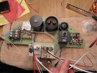
Tom has almost completed the wiring for the instrument panel. The layout has evolved somewhat so that a few critical circuit breakers are located on the panel and a few non-critical breakers are located on a sub-panel hidden behind the AV80R GPS/Moving map. The AV80R has buttons located on its edges so it has to be surface mounted on the face of the panel. It snaps out easily for use in the "land mode".


"Eyeball" fittings are used for the signal wire penetrations through the firewall. Having the right tools really comes in handy for tasks like sizing the holes in the two-piece eyeball to the appropriate size for the wire bundle. Les set these up in his mill and sized the holes as required.

Fuel Piping FWF


We completed the firewall-forward part of the fuel piping today. A Facet fuel pump is employed as a back-up to the engine driven pump and as a boost pump for priming at start-up. 3/8" tubing and hose is used throughout. A fuel flow transducer will supply info to the EIS engine monitor yielding fuel used, fuel remaining and time remaining. Others who have used this system have reported that it is very accurate.

The system is somewhat complicated by the addition of check valves to create separate and parallel systems for the two fuel pumps. This is probably overkill as the engine will likely run okay with gravity flow under most conditions.

Wednesday, January 20, 2010

Oil Cooler


The Jabiru uses an oil cooler adapter which fits between the engine block and the oil filter at the front of the engine. The supply and return lines run to the oil cooler which is located back on the firewall. The adapter normally has 1/8"NPT ports but we enlarged them to 1/4"NPT feeding 3/8" hoses.


Cooling air will be supplied by a NACA scoop and flow downward through the cooler. The hot air leaving the cooler will be ducted down to the intake and used for carb heat when necessary.