Welcome

*****Skyote #88 gets Bronze Lindy for "Airventure-Oshkosh 2016 Plans Built Champion"******


October, 2007

Welcome to "Skyotelog", the build record of Skyote #88. I assume that you are familar with the Skyote biplane. If not, you should visit http://www.skyote.org/ for a complete introduction to this unique but elusive biplane.

The posts are presented in reverse chronological order (newest first). Or you can click on one of the "Labels" to see all of the posts concerning a specific topic. Click on any photo for a larger image.

All my building experience is limited to Van's RV's so I have no experience with building tube and fabric or "plans building". I have much to learn so take everything I write with a grain of salt and reasonable skepticisim.


I do not intend to follow a "traditional" path for the construction of #88. I intend to employ low level technology and $ to reduce the construction time and difficulty where possible and practical. By low level technology I am referring to CAD, laser, waterjet, CNC. For example:

  • I have purchased a complete wing spar kit from Jerry Kerr.
  • A rib kit from Mr. Bartoe.
  • Brunton Flying Wires and Drag wires from Harvey Swack.
  • CNC profiled tube kits for the fuselage, tail feathers and landing gear from VR3.

In addition I have converted all of the wing fittings, brackets, links, lugs etc. to CAD and had them cut by water jet. I have designed a laser cut wing spar drill template/jig which positions the five spar components so that all of the holes can be drilled in a complete spar as an assembly. I plan to continue converting as many parts as I can to CAD so that I can reduce the "hand-made" components to a minimum.

Note: As of June 2015 I have over 100 CAD files which provide 600+ water jet cut parts for the Skyote.


While it takes a little time, converting the design to CAD is a great way to truly understand the drawings. plus a huge amount of information has been extracted from the rather complex drawings. This can be a great help to others in understanding and interpreting the design.


The Skyote is uniquely suited for conversion to CAD in that a "computer" was used in it's original design. I have read that Mr. Bartoe used a HP calculator to "compute" the design and dimensions of the Skyote. The plans show all of the critical dimensions to three decimal places for X,Y and Z axes.


Amazingly, when I put the design into CAD the resulting 3D models agree with Mr. Bartoe's thee decimal place dimensions about 99.9% of the time. I have found one discrepancy but less than 0.030"!


If you want to build your Skyote as cheaply as possible, or if you enjoy handcrafting the same parts over and over again then my approach to building is not for you!


If you want to build your Skyote in the minimum possible time with highly accurate parts then this approach may be the answer. I personally get a lot of satisfaction out of organizing the project so that it can be produced accurately. Hopefully some of this work will prove useful to others in the future.


Comments are welcome. I will respond as time permits

To receive email notices of new posts just enter your email address in the block at the left. It will be confidential, only Google will know!

Monday, December 12, 2011

Fabic Covering Begins

I have been saying "It's almost ready to cover" for the last year. Well covering has finally started. I am using Ceconite fabric products along with the "Ekobond" adhesive by Stewart Systems. This is the same stuff I tested on the sample panel almost a year back. I really like the ease of application compared to the traditional 'Poly-Tac" adhesive from Poly-Fiber. I have covered the horizontal and vertical stabilizers to the point of being ready for rib stitching and finish tapes.

Rather than go into much detail, I recommend that you visit the following videos on YouTube. These are videos posted by Stewart Systems showing the covering of a similar control surface. If the YouTube links are broken, you can find the same videos on the Stewart Systems site: http://www.stewartsystems.aero

www.youtube.com/watch?v=rl9I3FOA6Bc
www.youtube.com/watch?v=48OeYmvYHDM&feature=related
www.youtube.com/watch?v=KCmzyct6J-0&feature=related


Here goes nothing!


Bottom side covered. You can see the anti-chafe tapes on the ribs.


Finished with the basic wrap.


Repeat the process for the vertical stab.


I plan to cover the rudder and elevator before I rib-stitch and apply the finish tapes.

Wednesday, December 7, 2011

Elevator Travel Stops

When the elevator travel stops are installed the tail feathers will be ready to cover. The horizontal stab/elevator assembly was clamped to the welding table and leveled. A digital level was used to measure the angle of deflection.


I decided that the travel stops could be simple shims of the appropriate thickness to fill the gap between the elevator horn and the main spar tube of the horizontal stab when the elevator was at it's travel limit. The shim thickness was determined by inserting feeler gauges when the elevator was deflected the prescribed 24 degrees up and down.


The down stop needed a .160" shim and the up stop needed a shim .068". A collar was lathe turned to have a 3/4" ID with a .160" wall thickness. A sanding belt was used to reduce a portion of the wall thickness down to .068" thickness at the point of contact with the elevator horn. Half was cut away leaving a one piece shim to accomplish the up and down stop function.


This shows the shim in position from the top side.


This shows the shim from the bottom side with the elevator horn against the stop at 24 degrees deflection. .


After welding.


Close enough!

Wednesday, November 16, 2011

Simplicity Prevails


I would really like to have the 4 into 1 exhaust on the Skyote but it is just too bulky and heavy for the little Skyote. I managed to fit it all in but it would be difficult to get the cowl off plus the primary pipes were quite close to several important parts of the air frame. Did I mention that it was heavy? So I reverted to a system which is very similar to the set-up used on the O-200 powered Legend Cub. It is simple and sounds pretty good as well.


The finished pipes will be similar to this except the exhaust pipe will be more vertical and near the center. Also, no cabin heat muff.


Saturday, November 5, 2011

4 Into 1 Exhaust System


I purchased an exhaust mock-up kit from Aircraft Exhaust, Inc. It includes exhaust stack stubs, a 4 into 1 collector and instructions. I got the PVC pipe and fittings from Lowe's.


The PVC tubing and fittings are somewhat larger in diameter than the stainless tubing which will make up the actual exhaust system. This gives a little extra clearance in tight fitting areas.


All of the primary tubes should be of equal length.


The left front cylinder (#4, blue tape) is the furtherest from the collector so it sets the minimum primary tube length. All of the others have to include extra bends to achieve the same length.


It is important to leave sufficient clearance around the tubes to allow for engine shake and to prevent unwanted heat transfer. Radiation heat shields may be necessary in a few places.


Although I intend to use a battery/starter-only system, with no alternator, I still want to leave space for the alternator if I ever change my mind. Here the alternator is installed to check for clearance. This added a little complication to the challenge. I think I am getting pretty close to satisfying all of the requirements. I still need to work out a short (6" to 8" long) tail pipe and plan the mounting tabs and brackets. Aircraft Exhaust will recommend where the joints will need to be added to avoid cracking.

All of this took about 2-1/2 days and lots of PVC pipe!

Saturday, October 22, 2011

Final Paint Choice ???


With fabric covering soon to commence, I have been forced to make a final choice on color and design for the paint scheme. I stumbled across an image of the beautiful Pitcairn PA-7S on the EAA site. I think the black and yellow scheme suits the Skyote well. The Marchadier and Bridges planes already sport the Pitcairn logo so I am going to do something a little different there.

I decided to deviate from the PA-7 scheme by leaving the vertical stabilizer black rather than yellow. I think it makes the airplane look a little longer and also makes a good presentation for the Skyote logo. In regards to the logo, I think I will modify the standard logo with a surround that includes "Skyote Aeromarine".

I have a set of Matt Lahti's carbon fiber Cessna 140/170 wheel pants. The look pretty good on the airplane but I haven't decided if I will use them or not.


Thursday, October 20, 2011

The O-200 Is Here

The new Continental O-200 came today. I have included some shots of the engine still in its shipping crate an well as some after it has been hung on the engine mount. Looks like it is going to work out just fine. I was relieved to find that the engine mount lined up very nicely. The biggest challenge will be designing the exhaust system. I hope to have a 4-into-1 system with the collector exiting out the bottom of the cowl just in front of the firewall.


Monday, August 29, 2011

O-200 Engine Mount


The new engine mount for the Continental O-200 is fitted and tacked ready for final welding. Based on Hawkeye's aft C.G. condition and comparison to the weight and geometry of the Jab 3300, I decided to move the O-200 forward by 2" from the position specified in the plans. The plans call for 10" between the firewall and the back of the engine mount but this mount is 12".


At the risk of over doing a simple subject, I have put together a full sequence of fitting a tube to two parallel intersecting tubes using the "tube miter" software to print patterns. www.ozhpv.org.au/shed/tubemiter.htm


We are mating a 3/4" tube with a 1/2" tube. The tube miter program assumes that the 1/2" tube will pierce the 3/4" tube. This means that about 1/2 of the printed pattern will need to be discarded. Note that the tube miter program works in mm dimensions.


This is the part we need.


I use 3/8" flat stock to find the center line of the 3/4" tubes. Clamp the tube to the bench and mark each end on opposite sides. This will be used to align the patterns on each end.


Determine the length of the tube. This requires a little estimating using a tape measure and "eyeballing" the portion where the tape won't fit in. Align the pattern with the center lines on the tube and tape it in place.


Rough cut the tube on the band saw.


Grind the tube to match the pattern and check the fit. Because we are fitting a 3/4" tube to a 1/2" tube, the shaped end of the larger tube will need to be squeezed down for a better fit to the smaller tube.


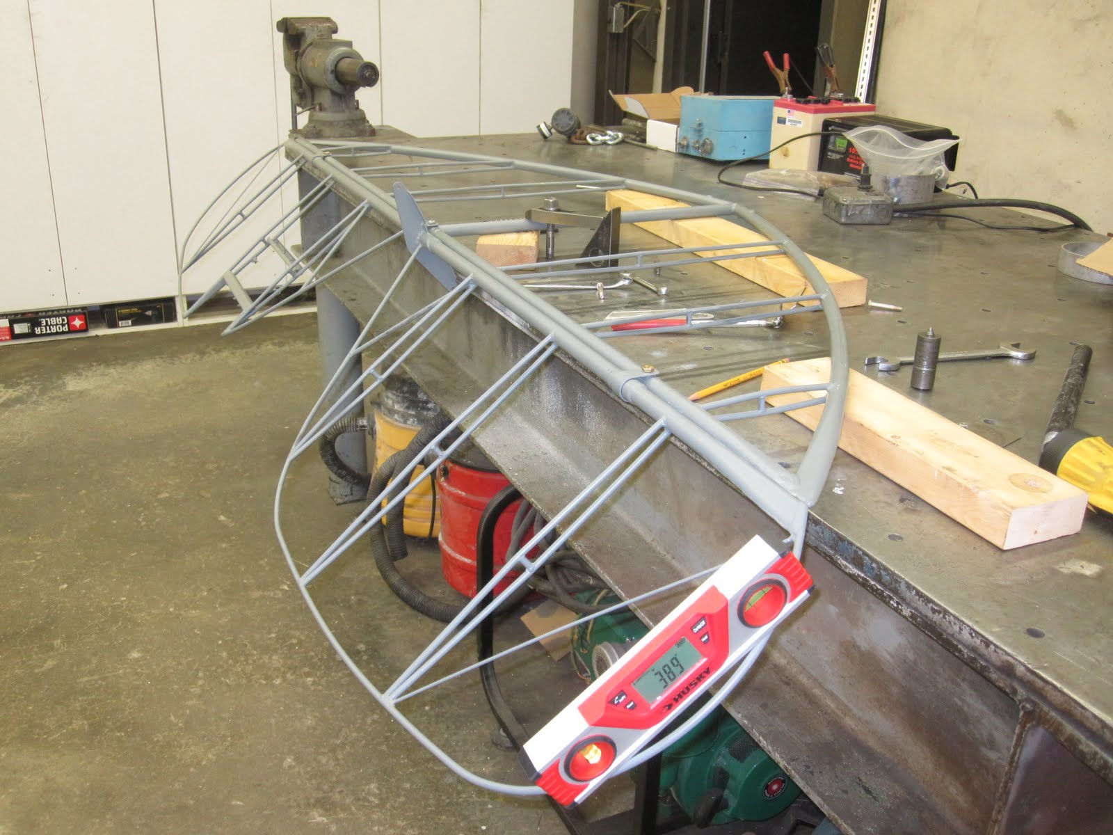
I was very pleased that I managed to cut and fit all of the tubes for this mount without scrapping a single tube!

Tuesday, August 16, 2011

New Engine Choice


The short version is: I have sold the Jabiru 3300 engine and ordered a custom built O-200 to replace it!

The long version is after reviewing the cooling problems others are having with the 3300 Jab and considering my options, I decided that it is best to make the change now rather than fight it for a long time and then possibly still have to make the change. I have already sold the Jab/prop/TBI and ordered a "slicked-up" O-200 from Don Swords of Griffin, GA. More about this engine later.

Refitting for the O-200 should go quickly as the plans provide all of the details for the installation. I think that most of the cowl can be salvaged but I have already started on the new engine mount.

In retrospect, all of the extra work required to adopt the Jab has set me back about a year from where I would be if I had originally gone with the O-200. Live and learn!

Thursday, July 7, 2011

Weight and Balance

I weighed the Skyote yesterday sans paint and covering. The empty weight (with engine oil) is currently 579 pounds. Assuming that paint and covering will weigh 60 pounds, I project a finished empty weight of 638 pounds with an empty plane C.G. of 15.5". According to the info supplied by Pete Bartoe, N27PB weighs 641 pounds empty with a C.G. of 12.3 inches.

I did the calculations for "normal" and extreme forward and extreme aft loadings. I distributed the projected 60 pounds additional for paint and fabric by area and location relative to the datum. The following table shows the results. (Click to enlarge.)


Here is a graph of the same data.


Note that the extreme forward condition is with a 100# pilot, no baggage and 100# fuel. The extreme aft position is with a 225# pilot, 20# baggage and 13# fuel, both of which are unrealistically extreme.

I am very pleased that the projected normal loading is right in the middle of the range at 19.5" while the extreme conditions are also still in the allowable range. It looks like NX88NX will be very forgiving of variations in loading.

Friday, June 10, 2011

Aileron Slave Push Rods


I have been putting off making the Aileron interplane push rods for too long. I turned 8 plugs from 4130 and drilled and tapped them to 1/4-28 while they were in the lathe.


The tubes were cut to length and "bird-mouthed" for welding on each end.


Ready for tack welding and assembly check before welding.