Welcome

*****Skyote #88 gets Bronze Lindy for "Airventure-Oshkosh 2016 Plans Built Champion"******


October, 2007

Welcome to "Skyotelog", the build record of Skyote #88. I assume that you are familar with the Skyote biplane. If not, you should visit http://www.skyote.org/ for a complete introduction to this unique but elusive biplane.

The posts are presented in reverse chronological order (newest first). Or you can click on one of the "Labels" to see all of the posts concerning a specific topic. Click on any photo for a larger image.

All my building experience is limited to Van's RV's so I have no experience with building tube and fabric or "plans building". I have much to learn so take everything I write with a grain of salt and reasonable skepticisim.


I do not intend to follow a "traditional" path for the construction of #88. I intend to employ low level technology and $ to reduce the construction time and difficulty where possible and practical. By low level technology I am referring to CAD, laser, waterjet, CNC. For example:

  • I have purchased a complete wing spar kit from Jerry Kerr.
  • A rib kit from Mr. Bartoe.
  • Brunton Flying Wires and Drag wires from Harvey Swack.
  • CNC profiled tube kits for the fuselage, tail feathers and landing gear from VR3.

In addition I have converted all of the wing fittings, brackets, links, lugs etc. to CAD and had them cut by water jet. I have designed a laser cut wing spar drill template/jig which positions the five spar components so that all of the holes can be drilled in a complete spar as an assembly. I plan to continue converting as many parts as I can to CAD so that I can reduce the "hand-made" components to a minimum.

Note: As of June 2015 I have over 100 CAD files which provide 600+ water jet cut parts for the Skyote.


While it takes a little time, converting the design to CAD is a great way to truly understand the drawings. plus a huge amount of information has been extracted from the rather complex drawings. This can be a great help to others in understanding and interpreting the design.


The Skyote is uniquely suited for conversion to CAD in that a "computer" was used in it's original design. I have read that Mr. Bartoe used a HP calculator to "compute" the design and dimensions of the Skyote. The plans show all of the critical dimensions to three decimal places for X,Y and Z axes.


Amazingly, when I put the design into CAD the resulting 3D models agree with Mr. Bartoe's thee decimal place dimensions about 99.9% of the time. I have found one discrepancy but less than 0.030"!


If you want to build your Skyote as cheaply as possible, or if you enjoy handcrafting the same parts over and over again then my approach to building is not for you!


If you want to build your Skyote in the minimum possible time with highly accurate parts then this approach may be the answer. I personally get a lot of satisfaction out of organizing the project so that it can be produced accurately. Hopefully some of this work will prove useful to others in the future.


Comments are welcome. I will respond as time permits

To receive email notices of new posts just enter your email address in the block at the left. It will be confidential, only Google will know!

Friday, May 22, 2015

Painting the Main Gear


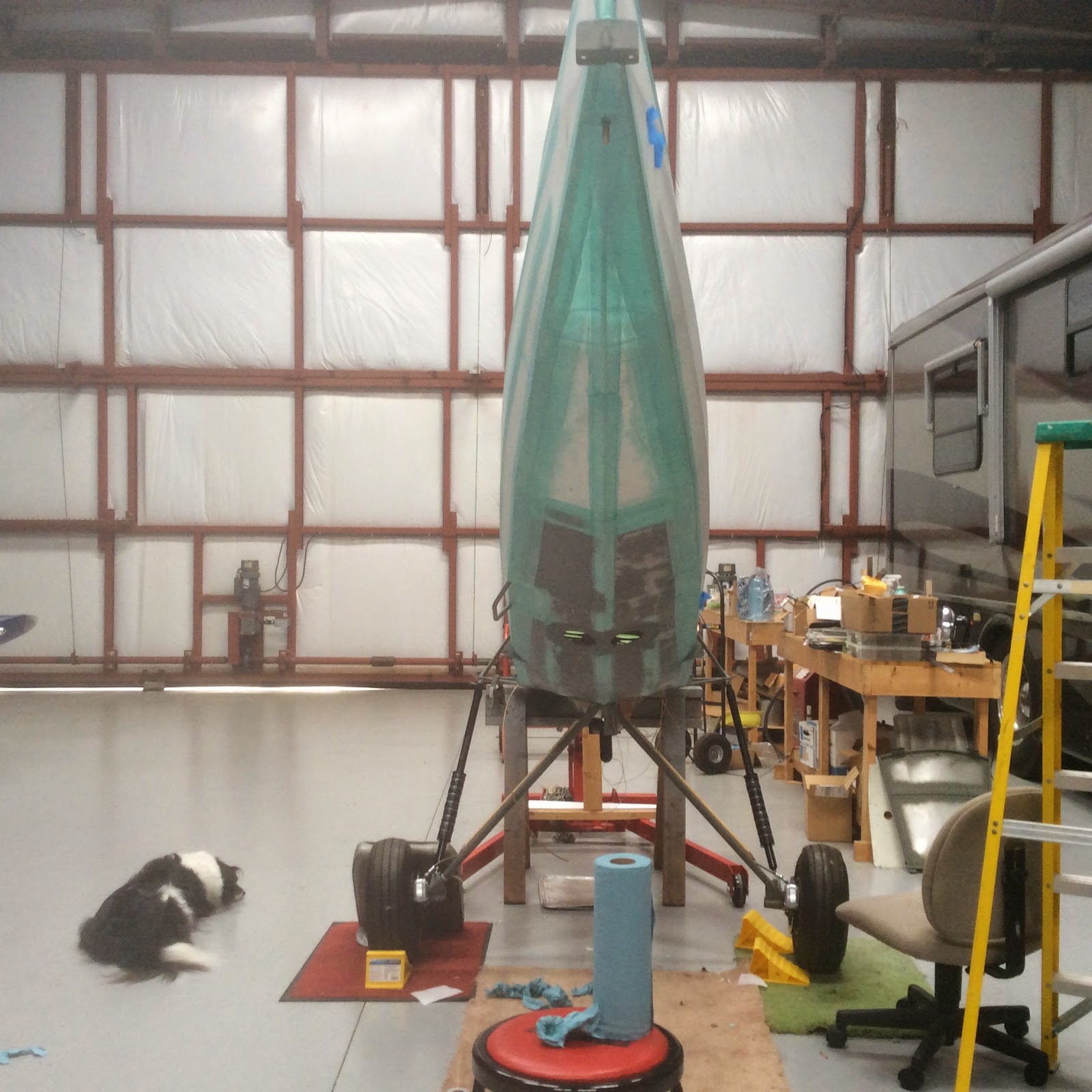
Grounded! The fuse sadly waits while its landing gear is prepped and painted.

 The gear has been primed with PPG DP-40 epoxy primer and the fiberglassed fairings prepped with hi-build primer. I mounted both gear legs on one arm of the wing rotisserie so that they could be rotated to get to all of the weird angles.

All ready for the final top coats.

 Painting with the brake lines installed was a big PITA. I would not do that again.

Ready to install on the fuselage.

Here the gear strut is prepped and re-primed with DP=40 prior to adding the final top-coats.


Done! I plan to put #88 back on its gear tomorrow.

Covering and painting the fuse on the gear with the engine in place was also a big mistake. I wish I had covered and painted the fuse on a rotisserie. It would have been quicker, easier and I could have done a better job overall.

Thursday, May 14, 2015

Fiber Glassing Landing Gear Fairings

Today I added fiberglass wraps for the landing gear /brake line fairings. I used medium weight biax glass cloth and West Systems 105/205 resin. I wrapped the brake lines with clear packing tape so that the epoxy would not glue them in place. Hopefully the fairings will survive the upcoming abuse a little better. Note that I have added flanged adapters to allow bolt on axles. THis mod is covered in earlier posts.


 Balsa fairing glued to landing gear tube.  A little body filler has been added to smooth the joint.


 Fiberglass cloth attached to fairing.  No resin yet. I used an old modeler's trick of using CA instant adhesive to tack the cloth in place.


 Here the ends of the cloth have been trimmed and tucked, again using CA to tack in place. No resin yet.


Saturated with West systems resin. Almost makes the cloth invisible,  I hope to get the gear primed and painted tomorrow.

Tuesday, May 12, 2015

Painting Center Section

I shot the white Ekoprime early this morning followed by the Federal Yellow EkoPoly this afternoon. I am slowly getting a little better laying the paint on.  Also I was talking to Ken at Stewart Systems yesterday and he gave me new mix ratios for the EkoPoly. It is now 4:1:1 EloPoly/catalyst/water which is quite different from the old numbers that I had been using. I think it works better with the new ratios. I will eventually learn to paint, just about the time I finish this project!


 Tank skins in white EkoPrime.

 Bottom view of tank.

 It's yellow now.


 The formed trailing edge skins show well in this view.


Sight gage made from a Stearman part.

Fuel outlet.

Center Section Detail Photos


Just a few shots of the center section with the top cover removed. The design and construction of the aft section of my center section including the grab handle is not per plans.


Tuesday, May 5, 2015

Center Section Prep


I have decided to paint and install the upper wing center section before I paint the remaining wings. This will allow the installation the wings as they are painted.  I am apprehensive about putting newly painted wings in the storage rack, I fear that they will get impressions in the paint as they sit


There are some older posts showing the design and construction of the aluminum plate handle.  The top skin was extended rearward to incorporate and tie in the handle.  More weight but slick and strong.

My buddy Tom is helping me close out the aft bottom skin.  We thought it would require several breaks to form the concave bottom.  Tom discovered the skins would conform with no breaks.  I will try to get a better shot to show this more clearly. The compound curves of outboard aft skins make the trailing edge very strong and stiff. If all goes to plan this will soon be yellow.

Sunday, May 3, 2015

Yellow Wing

I painted the 1st wing yesterday. It turned out pretty well although I still tend to apply the paint a little too heavy. No runs or sags just more weight added to the airplane. Having said that, I am not certain that the yellow would cover with any less paint. Don't even think about painting yellow over  anything but white primer.
 1st. Wing in white EkoPrime ready for finish coats.


Federal yellow EkoPoly.

In the daylight.


The rotisserie is indispensable. If you don't want to make a cantilever rotisserie then you will need to provide some sort of support at the wing tip. I guess it could be in the form of a nav light mounting pad.

Thursday, April 30, 2015

Painting the Wings


I had a rotisserie left over from the RV7A project. It was originally designed to support the wing on both ends but it was modified to have two cantilever arms which extend about 6 feet through the rib lightning holes. There was an old variable speed gearmotor on the shelf so it was tacked on so now all I have to do is flip a switch to to put the wing in exactly the right position.  Also, I don't have to wait for one side to dry before I paint the other.  This is going to be a huge help in getting a good job on the wings.

Drive end.

Two brushed cross-coats of EkoFill UV protectant primer

After four sprayed coats of EkoFill primer on top of four brushed coats.
Ready for the white EkoPrime primer/sealer. I really like the EkoPrime product.  It can also be used on metal although I have not tried that yet.


Yellow Tail


Here is a daylight shot of the yellow stabilizer.
The stabilizer was painted in the horizontal position so it flowed out much better.

Wednesday, April 29, 2015

More Paint Progress

I painted the horizontal tail parts today.  The color is Federal Yellow. 
I applied white Ekoprime  undercoats to make the yellow color pop.
The fluorescent shop lighting makes the color look a little green. 
I will try to get a shot in natural light soon. Now its time to start on the wings which will also be yellow.


 Two cross coats of White EkoPrime sanded between coats.


Four cross coats of Federal yellow

Limerick


This photo reminds me of an old limerick:

There was a young man from Boston.
He drove a tiny baby Austin.
There was room for his ass and a gallon of gas.
His balls hung out and he lost them!

May just be the perspective of the photo but it shows how tiny the Skyote fuselage actually is.
Thankfully, Pete included enough room for all the vital body parts but just barely!

Saturday, April 25, 2015

Paint Progress

Recent Fabric Painting Progress

Here are a few photos of painting from the past week. I am using Stewart Systems products.

All parts get two brushed cross-coats of Ekofill primer then three additional sprayed cross-coats all lightly sanded between each coat. 

Then three sprayed cross coats of Ekopoly Premium catalyzed urethane. For anyone considering using Stewart Systems products a word of advice. Study their excellent on-line videos carefully then do EXACTLY as they say. The application technique required is NOT like conventional paint. It is very easy to fall into old habits in the middle of painting!
If you do you WILL put on TOO MUCH paint. Ask me how I know. It is like trying to un-learn how to ride a bicycle. I guess you can teach an old dog new tricks but it is really hard for the old dog. Actually, it is not difficult just different.

Also good lighting so you can see the work surface is VERY important. This proved to be very important when painting black. In retrospect, I would have removed the engine and landing gear and used a rotisserie for the fuse as I will be doing for the wings. Painting the bottom of the fuse was a real pain for an old guy 

Lastly, this paint system, like most, works best when the parts are in the horizontal position. I painted the vertical stab and rudder in the vertical position. They came out okay but I am sure they would have been a little better if painted in the horizontal. This paint flows nicely and a horizontal orientation helps that to happen.

All of the metal parts including cowling, boot cowl and struts have been painted black so it's time to break out the yellow for the wings and horizontal tail parts.


Paint Scheme


These were the first actual parts I painted using the Stewart Systems Ekopoly.
As I said, I fell into old habits and applied the paint too aggressively.
The gloss is good but more "texture" than I wanted.
I should have painted them in the horizontal position.


Ready for the trek from my hangar to my home shop.


Nice view of the fuse in primer ready to paint.
The shop light is in position on the floor to light up the belly which was painted first.

Still wet!


Next day, out of the paint booth.

Not great but passable at 10 feet!


Saturday, April 18, 2015

Fuselage progress

I have been pushing to get the fuse ready for painting this coming week. Good weather is predicted for most of the week and I don't want to miss the opportunity.


 Applying trim tapes.

Working on the belly is no fun with bi-focals!

First brush coat of primer.

Three cross coats of primer, sanded between coats.


Ready to be taped out, then three more spray coats of primer before the top coats are applied.

Tuesday, February 17, 2015

Pitot Tube Installation

I decided to mount the pitot tube on the access port door on the bottom of lower wing. This makes access easy for connecting the flexible tubing to the pitot. This is a Van's RV stainless tube which I had from a previous project.