 My prop flange is about 2" forward of the original design position in hopes of having a more forward C.G. .
  I think I will shorten the engine exhaust and the carb heat exhaust pipes a little and add a 45 degree turn back to the engine exhaust pipe.

This blog documents the construction of Skyote Biplane #88.
My prop flange is about 2" forward of the original design position in hopes of having a more forward C.G. . I think I will shorten the engine exhaust and the carb heat exhaust pipes a little and add a 45 degree turn back to the engine exhaust pipe.


 The new cowl for the O-200 is almost complete. Still working on the inlet air box which covers the carb/carb heat diverter/air filter. The inlet is designed around a K&N filter from a big Yamaha motorcycle.

 This is a view of the carb heat box which covers the junction of the left and right pipes with the vertical tail pipe. This should be a good hot spot and generate plenty of carb heat. It is also inside the cowl rather than hanging out in the breeze.
 The pipes are just resting on the engine mounts in these photos and are not bolted up to the engine.
 I found what appears to be a new O-200 tank. This will replace the one which has been welded around the filler neck. Tanks in good shape are really scarce.


 Carbon Fiber trim tab in place.

 One side of the rudder covered.
 Forming the seam for the second side.
 I forgot to get a picture, but when the fabric is shrunk, cuts such as the one around the rudder horn create quite a gap. I used a piece of 0.020" aluminum to create "close out plates" around the horn and hinge.


 The aluminum sheet assures a clean, crisp, stable edge around the cut.

 This was also done at the elevator and rudder hinge cuts.
  The tip of a hot soldering iron was used to trim the fabric to the edge of the aluminum.
 The soldering iron was also used to create holes for the rib stitches. Be careful! If you drop the iron it will go right through the fabric! No, it's a miracle, but I didn't do it!


 Adding the leading edge perimeter tape to bottom side of the horizontal stab.
 Here goes nothing!
 Bottom side covered. You can see the anti-chafe tapes on the ribs.
 Finished with the basic wrap.
 Repeat the process for the vertical stab.
 I plan to cover the rudder and elevator before I rib-stitch and apply the finish tapes.
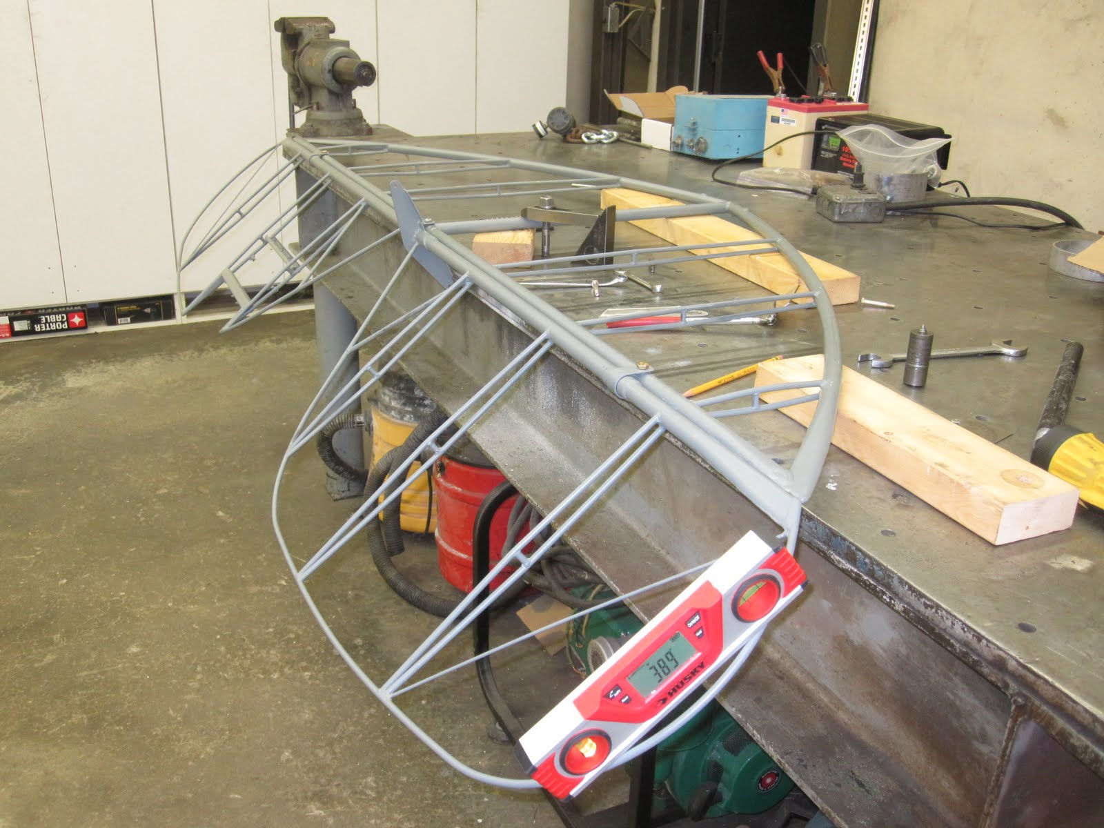 When the elevator travel stops are installed the tail feathers will be ready to cover. The horizontal stab/elevator assembly was clamped to the welding table and leveled. A digital level was used to measure the angle of deflection.
 I decided that the travel stops could be simple shims of the appropriate thickness to fill the gap between the elevator horn and the main spar tube of the horizontal stab when the elevator was at it's travel limit. The shim thickness was determined by inserting feeler gauges when the elevator was deflected the prescribed 24 degrees up and down.
  The down stop needed a .160" shim and the up stop needed a shim .068". A collar was lathe turned to have a 3/4" ID with a .160" wall thickness. A sanding belt was used to reduce a portion of the wall thickness down to .068" thickness at the point of contact with the elevator horn. Half was cut away leaving a one piece shim to accomplish the up and down stop function.
 This shows the shim in position from the top side.
 This shows the shim from the bottom side with the elevator horn against the stop at 24 degrees deflection. .
 After welding.
 Close enough!


