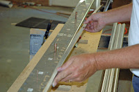
We chose to use laser cut drill guides to aid in quickly and accurately drilling the wing spars. The drill guide is essentially a replica of the spar web but laser cut from 0.125" CRS. The spar web and the spar angles or "caps" are assembled between two drill guide plates and matched drilled. Every single hole that will eventually be in the spar is drilled at this time. The entire operation takes about 35 minutes and completely eliminates the laying out of hole centers before drilling. It does require a very thorough understanding of the wing geometry in order to correctly model the spar in CAD. You will also want to carefully check and recheck your drill guides for errors before you scrap a lot of expensive spar parts! If you find a mistake in your drill guides it is easy to weld up the offending holes and manually drill them in the correct position. Ask me how I know! It is also important to thoroughly de-burr and smooth the drill guide plates as the laser leaves lots of sharp edges which can scratch the spar components.

The first step involves positioning the spar web between the appropriate drill guide plates and drilling tooling holes to accurately hold the spar web and angles in position for the subsequent steps. We use tooling holes spaced about 12 inches apart. The tooling holes are drilled into the hardwood spine on the table so that clecoes inserted into the tooling holes also hold the components to the bench.

This also a good time to mark the tip of the spar web for trimming for the taper.
After the tooling holes are drilled the guide plates are separated and and then re stacked with the spar cap spacers in place.
 The above photo shows the bottom guide plate with spacers in place. The spacers will maintain the correct dimension between the flanges of the spar caps. The wire pins hold the spacers in position while all of the components are assembled. Next comes the spar web.

Then the next set of spacers.

Then the upper Drill guide plate.

Now a few of the pins are removed and replaced with clecoes to secure all of the components so that the spar angles can be inserted.

After all of the spar angles are in place and all of the pins are replaced with clecoes it's time to begin drilling. We used blocks and a clamp at each tooling station to be certain that the legs of the spar angles were seated against the spacers. We also used hardened drill guide bushings o assure that the drill bit was properly aligned for drilling.


We also used drill guide bushings for the larger holes.

Then drill,drill,drill,drill............drill!
Following completion of all drilling (about 35 minutes) we marked the inboard ends of the spar angles for trimming at the appropriate angles.

After drilling the spar components are ready for deburring. In this photo they have been clecoed back together to keep all of the components together and separate from other spars.

