Welcome

*****Skyote #88 gets Bronze Lindy for "Airventure-Oshkosh 2016 Plans Built Champion"******


October, 2007

Welcome to "Skyotelog", the build record of Skyote #88. I assume that you are familar with the Skyote biplane. If not, you should visit http://www.skyote.org/ for a complete introduction to this unique but elusive biplane.

The posts are presented in reverse chronological order (newest first). Or you can click on one of the "Labels" to see all of the posts concerning a specific topic. Click on any photo for a larger image.

All my building experience is limited to Van's RV's so I have no experience with building tube and fabric or "plans building". I have much to learn so take everything I write with a grain of salt and reasonable skepticisim.


I do not intend to follow a "traditional" path for the construction of #88. I intend to employ low level technology and $ to reduce the construction time and difficulty where possible and practical. By low level technology I am referring to CAD, laser, waterjet, CNC. For example:

  • I have purchased a complete wing spar kit from Jerry Kerr.
  • A rib kit from Mr. Bartoe.
  • Brunton Flying Wires and Drag wires from Harvey Swack.
  • CNC profiled tube kits for the fuselage, tail feathers and landing gear from VR3.

In addition I have converted all of the wing fittings, brackets, links, lugs etc. to CAD and had them cut by water jet. I have designed a laser cut wing spar drill template/jig which positions the five spar components so that all of the holes can be drilled in a complete spar as an assembly. I plan to continue converting as many parts as I can to CAD so that I can reduce the "hand-made" components to a minimum.

Note: As of June 2015 I have over 100 CAD files which provide 600+ water jet cut parts for the Skyote.


While it takes a little time, converting the design to CAD is a great way to truly understand the drawings. plus a huge amount of information has been extracted from the rather complex drawings. This can be a great help to others in understanding and interpreting the design.


The Skyote is uniquely suited for conversion to CAD in that a "computer" was used in it's original design. I have read that Mr. Bartoe used a HP calculator to "compute" the design and dimensions of the Skyote. The plans show all of the critical dimensions to three decimal places for X,Y and Z axes.


Amazingly, when I put the design into CAD the resulting 3D models agree with Mr. Bartoe's thee decimal place dimensions about 99.9% of the time. I have found one discrepancy but less than 0.030"!


If you want to build your Skyote as cheaply as possible, or if you enjoy handcrafting the same parts over and over again then my approach to building is not for you!


If you want to build your Skyote in the minimum possible time with highly accurate parts then this approach may be the answer. I personally get a lot of satisfaction out of organizing the project so that it can be produced accurately. Hopefully some of this work will prove useful to others in the future.


Comments are welcome. I will respond as time permits

To receive email notices of new posts just enter your email address in the block at the left. It will be confidential, only Google will know!

Friday, July 25, 2008

The Firewall Fits!


We had a chance to check out the stainless steel firewall today with good results. The part was cut by waterjet complete with 75 rivet holes for the perimeter angle and the main engine mount holes.

Tail Feathers Progress


The horizontal Stab and the elevators are almost done. The tail section is much easier than the fuselage or landing gear as the geometry is relatively straight forward. The VR3 tail kit has worked out well so far.

Tuesday, July 15, 2008

Tail Feathers First Look

This is the first look at the VR3 kit for the tail feathers. This section of the airplane will be relatively straight forward compared to the previous sections as the geometry is essentially flat with no obscure angles. As usual, the VR3 parts fit perfectly so far. The only tricky part is squishing the ends of the large diameter tubes to mate up with the smaller tubes so that the "squish" all winds up on one side of the large tube. More on this later.

The tail kit contains 93 pieces and sells for $1232 plus $150 shipping and handling. All of the tubes are pre-bent so the shipping carton for the tail is pretty big.

Saturday, July 12, 2008

More Leg Room


Today we located the new design rudder /brake pedals in the fuselage. With me sitting in the fuse (6'-1" long legs) we were able measure for a reserve header tank to be located above the rudder/brake pedal assembly. That's Dale Doane holding the pedal assembly and "Chief Machinist" Les Kanna looking on. Looks like I need to go on the "Skyote Weight Loss Program" as there is more excess weight on my butt than I could ever trim off the Skyote.

Because the new assembly is only 8 1/2" tall there is quite a bit of space available between the top of the rudder/brake pedal assembly and the bottom of the regular header tank. The attached CAD image is a rough but conservative estimate of the tank that can be fitted with out intrusion on the knees or pedals. It has a volume of 1437 cubic inches which is 6+ gallons. This is a huge addition which will extend the range of Skyote #88 by more than 1 hour. The fat end (firewall) is 5.5" x 15" while the thin end (instrument panel) is 3.5" x 19" with a fore and aft dimension of 20"


The new pedal assembly looks like it will also yield additional leg room. The actual amount is yet to be determined but it looks like it will be more than 1" greater than stock and maybe 2" greater.

Wednesday, July 9, 2008

Rudder/Brake Pedals


This the first set of rudder/brake pedals built to the Skyote/Van's hybrid design that I proposed earlier. Just tack welded at this time. This is a view of the left pedal from the aft (pilots) side.
The modified design has the potential of creating more leg room with its aft mounted master cylinders.
There is also the potential for a reserve header tank above the pedal assembly due to the shorter vertical dimension of this design. Looks like maybe 2 to 3 gallons can be squeezed in above the pedals.
Both the overhead pivot and the pivot at the base of the pedals have non lubricated nylon bushings. I chose Grove master cylinders and they look good so far. This design has fewer parts than the original Skyote design. Moving the master cylinder from behind the pedals eliminates the need for the bell crank assembly which frees up space for the new pedal assembly to move forward. This arrangement is commonly used on Van's RV airplanes and works quite well. I think the new design has combined the best of both approaches.

Thursday, July 3, 2008

Spar Drilling Sequence

The following is a step by step account of the procedure Tom and I used to drill the Skyote spars.
We chose to use laser cut drill guides to aid in quickly and accurately drilling the wing spars. The drill guide is essentially a replica of the spar web but laser cut from 0.125" CRS. The spar web and the spar angles or "caps" are assembled between two drill guide plates and matched drilled. Every single hole that will eventually be in the spar is drilled at this time. The entire operation takes about 35 minutes and completely eliminates the laying out of hole centers before drilling. It does require a very thorough understanding of the wing geometry in order to correctly model the spar in CAD. You will also want to carefully check and recheck your drill guides for errors before you scrap a lot of expensive spar parts! If you find a mistake in your drill guides it is easy to weld up the offending holes and manually drill them in the correct position. Ask me how I know! It is also important to thoroughly de-burr and smooth the drill guide plates as the laser leaves lots of sharp edges which can scratch the spar components.

The first step involves positioning the spar web between the appropriate drill guide plates and drilling tooling holes to accurately hold the spar web and angles in position for the subsequent steps. We use tooling holes spaced about 12 inches apart. The tooling holes are drilled into the hardwood spine on the table so that clecoes inserted into the tooling holes also hold the components to the bench.

This also a good time to mark the tip of the spar web for trimming for the taper.

After the tooling holes are drilled the guide plates are separated and and then re stacked with the spar cap spacers in place.
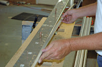
The above photo shows the bottom guide plate with spacers in place. The spacers will maintain the correct dimension between the flanges of the spar caps. The wire pins hold the spacers in position while all of the components are assembled. Next comes the spar web.


Then the next set of spacers.

Then the upper Drill guide plate.


Now a few of the pins are removed and replaced with clecoes to secure all of the components so that the spar angles can be inserted.

After all of the spar angles are in place and all of the pins are replaced with clecoes it's time to begin drilling. We used blocks and a clamp at each tooling station to be certain that the legs of the spar angles were seated against the spacers. We also used hardened drill guide bushings o assure that the drill bit was properly aligned for drilling.


We also used drill guide bushings for the larger holes.

Then drill,drill,drill,drill............drill!
Following completion of all drilling (about 35 minutes) we marked the inboard ends of the spar angles for trimming at the appropriate angles.


After drilling the spar components are ready for deburring. In this photo they have been clecoed back together to keep all of the components together and separate from other spars.