Welcome

*****Skyote #88 gets Bronze Lindy for "Airventure-Oshkosh 2016 Plans Built Champion"******


October, 2007

Welcome to "Skyotelog", the build record of Skyote #88. I assume that you are familar with the Skyote biplane. If not, you should visit http://www.skyote.org/ for a complete introduction to this unique but elusive biplane.

The posts are presented in reverse chronological order (newest first). Or you can click on one of the "Labels" to see all of the posts concerning a specific topic. Click on any photo for a larger image.

All my building experience is limited to Van's RV's so I have no experience with building tube and fabric or "plans building". I have much to learn so take everything I write with a grain of salt and reasonable skepticisim.


I do not intend to follow a "traditional" path for the construction of #88. I intend to employ low level technology and $ to reduce the construction time and difficulty where possible and practical. By low level technology I am referring to CAD, laser, waterjet, CNC. For example:

  • I have purchased a complete wing spar kit from Jerry Kerr.
  • A rib kit from Mr. Bartoe.
  • Brunton Flying Wires and Drag wires from Harvey Swack.
  • CNC profiled tube kits for the fuselage, tail feathers and landing gear from VR3.

In addition I have converted all of the wing fittings, brackets, links, lugs etc. to CAD and had them cut by water jet. I have designed a laser cut wing spar drill template/jig which positions the five spar components so that all of the holes can be drilled in a complete spar as an assembly. I plan to continue converting as many parts as I can to CAD so that I can reduce the "hand-made" components to a minimum.

Note: As of June 2015 I have over 100 CAD files which provide 600+ water jet cut parts for the Skyote.


While it takes a little time, converting the design to CAD is a great way to truly understand the drawings. plus a huge amount of information has been extracted from the rather complex drawings. This can be a great help to others in understanding and interpreting the design.


The Skyote is uniquely suited for conversion to CAD in that a "computer" was used in it's original design. I have read that Mr. Bartoe used a HP calculator to "compute" the design and dimensions of the Skyote. The plans show all of the critical dimensions to three decimal places for X,Y and Z axes.


Amazingly, when I put the design into CAD the resulting 3D models agree with Mr. Bartoe's thee decimal place dimensions about 99.9% of the time. I have found one discrepancy but less than 0.030"!


If you want to build your Skyote as cheaply as possible, or if you enjoy handcrafting the same parts over and over again then my approach to building is not for you!


If you want to build your Skyote in the minimum possible time with highly accurate parts then this approach may be the answer. I personally get a lot of satisfaction out of organizing the project so that it can be produced accurately. Hopefully some of this work will prove useful to others in the future.


Comments are welcome. I will respond as time permits

To receive email notices of new posts just enter your email address in the block at the left. It will be confidential, only Google will know!

Thursday, October 9, 2008

Spar Party # 3

Greg Swanson now has a complete set of drilled spars for his Skyote. Greg drove over in early October and with Tom's help we managed another 4-1/2 hour spar drilling session. This is the third complete sets of spars to be drilled using these jigs. That big smile is because Gregg is drilling the last of eight spars for his Skyote!


Marking all of the components before disassembling and packing for the return trip.


Alabama bound!

Great Picture


David Teel sent me these pictures of the wings he and Glenn have built for Glenn's Skyote. A real work of art. If you check previous posts in this blog you will see that the spars for these wings were just drilled August 15, 2008. A tip of the cap to Glenn and David for such beautiful and speedy work!

Engine Mounted on Stand


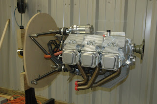
I decided to make up two engine mounts. The "prototype" above is made from scrap tubing and tack welded by me. I also cut out a profile of the firewall using MDF and mounted it with the engine. I will use this rig to locate all of the firewall forward components and to design the cowling. I still have to locate the diagonal brace between the left and right sides of the mount.

The second set of tubes will be welded by Dale after we are sure that everything is set with the prototype mount.