Welcome

*****Skyote #88 gets Bronze Lindy for "Airventure-Oshkosh 2016 Plans Built Champion"******


October, 2007

Welcome to "Skyotelog", the build record of Skyote #88. I assume that you are familar with the Skyote biplane. If not, you should visit http://www.skyote.org/ for a complete introduction to this unique but elusive biplane.

The posts are presented in reverse chronological order (newest first). Or you can click on one of the "Labels" to see all of the posts concerning a specific topic. Click on any photo for a larger image.

All my building experience is limited to Van's RV's so I have no experience with building tube and fabric or "plans building". I have much to learn so take everything I write with a grain of salt and reasonable skepticisim.


I do not intend to follow a "traditional" path for the construction of #88. I intend to employ low level technology and $ to reduce the construction time and difficulty where possible and practical. By low level technology I am referring to CAD, laser, waterjet, CNC. For example:

  • I have purchased a complete wing spar kit from Jerry Kerr.
  • A rib kit from Mr. Bartoe.
  • Brunton Flying Wires and Drag wires from Harvey Swack.
  • CNC profiled tube kits for the fuselage, tail feathers and landing gear from VR3.

In addition I have converted all of the wing fittings, brackets, links, lugs etc. to CAD and had them cut by water jet. I have designed a laser cut wing spar drill template/jig which positions the five spar components so that all of the holes can be drilled in a complete spar as an assembly. I plan to continue converting as many parts as I can to CAD so that I can reduce the "hand-made" components to a minimum.

Note: As of June 2015 I have over 100 CAD files which provide 600+ water jet cut parts for the Skyote.


While it takes a little time, converting the design to CAD is a great way to truly understand the drawings. plus a huge amount of information has been extracted from the rather complex drawings. This can be a great help to others in understanding and interpreting the design.


The Skyote is uniquely suited for conversion to CAD in that a "computer" was used in it's original design. I have read that Mr. Bartoe used a HP calculator to "compute" the design and dimensions of the Skyote. The plans show all of the critical dimensions to three decimal places for X,Y and Z axes.


Amazingly, when I put the design into CAD the resulting 3D models agree with Mr. Bartoe's thee decimal place dimensions about 99.9% of the time. I have found one discrepancy but less than 0.030"!


If you want to build your Skyote as cheaply as possible, or if you enjoy handcrafting the same parts over and over again then my approach to building is not for you!


If you want to build your Skyote in the minimum possible time with highly accurate parts then this approach may be the answer. I personally get a lot of satisfaction out of organizing the project so that it can be produced accurately. Hopefully some of this work will prove useful to others in the future.


Comments are welcome. I will respond as time permits

To receive email notices of new posts just enter your email address in the block at the left. It will be confidential, only Google will know!

Thursday, January 27, 2011

Center Section Handle

It would be really helpful to have something to hold on to while I coax my 70 year old bones into the cockpit. The trailing edge of the upper wing center section seems to be a good location. One possibility is to replace the 3/8" steel tube trailing edge with combination trailing edge/handle cut from 1/4" aluminum plate. This would allow the handle to be incorporated into the trailing edge and also provide a better interface for attaching to the ribs. I made a prototype from 1/4" plywood and it looks like it will work okay. The middle ribs will be cut so that the upper flange of the ribs laps over the aluminum plate.


I decided to add some tabs to aid in attachment to the ribs. The final part was water-jet cut from 1/4" 6061-T6.


Center section ribs marked for Cutting.


Cutting with an abrasive wheel worked well.


The handle/trailing edge is now in the final position flush with the upper surface of the ribs. The next step will be to install 0.020" skins to tie the handle to the center section ribs and the aft spar.

Monday, January 10, 2011

Fabric/Painting Test Panel


With the covering/painting phase of the project on the near horizon I have started thinking about the alternatives. I have attended EAA workshops for both TIG welding and fabric covering. The welding class convinced me that I would never reach the skill level required to do a top notch job on the Skoyte fuselage structure. The fabric school, however, convinced me that I have a good chance of doing an acceptable job covering the Skyote myself. I have participated in a couple of covering jobs since the workshop, both using the PolyFiber system and PolyTone paint.
http://www.polyfiber.com/

I have also studied the line of waterborne adhesives and paints offered by Stewart Systems. I certainly like the user friendly qualities of the waterborne products. Stewart also has an excellent set of DVD's which illustrate the covering and finishing process in great detail. I think they are worth watching no matter which system you choose. You can go to: http://www.stewartsystems.aero/ or you can go to YouTube and enter "Stewart Systems" to see the videos.

I decided to make up a test panel and cover and finish it with Stewart products. This will give me a good comparison of the two systems. I am leaning toward the Stewart products but I want to have a little more experience with it before I make the final decision.

I glued up an imaginary airfoil panel using some plywood scraps and other junk. It is about 20"x20".


Stewart Systems Ekobond adhesive is blue/green in color. Unlike Polyfiber Polytac adhesive it has no oder. I covered this test panel in the kitchen during a recent snow with no complaints from my wife!

I am keeping up with the uncovered, covered, primed and painted weights of the test panel.

The panel in the photo below has two "cross-coats" of Ekofill primer/filler/UV barrier applied by brush. The next two coats of Ekofill will be sprayed. The color is actually a charcoal grey.

Two coats of EkoFill white provides a good base for the "Federal Yellow" EkoPoly topcoat.


Four "cross-coats" of EkoPoly gave good coverage for the final top coat. The EkoPoly gives a nice high gloss finish. I got just a little bit of orange peel. The small test panel didn't allow much opportunity to experiment with gun settings but I am only off about one click from ideal.

Friday, January 7, 2011

Wheel alignment completed.

The wheels and axles were were reinstalled. Skyote #88 now has zero toe-in when it sits in the three point position.

The 1.8 degree axle correction is visible in the photo below. This shot is from above the right wheel with the airplane facing to the right.

Wednesday, January 5, 2011

Toe-in Correction Contd.

Rather than use shims to correct the toe-in problem we decided to machine the face of the axle flange to give the same results. This was done by holding the axle in a vertical chuck and tilting the head of the Bridgeport 1.8 degrees. A fly-cutter was then used to face off the axle flange. Robbie Grove confirmed that these axles are way over built for the Skyote application. A maximum of 0.062" of material will be removed from the flange.

We used a digital level to check the angle of the milling head.

Axle held in vertical vise mounted on the BridgePort table.

Fky-cutter pass in progress.

The photo below shows the 1.8 degree angle on the face of the axle flange. The axles will be reinstalled later this week. The toe should now be zero in the three point attitude. Any further adjustments can be done with shims which are available from Grove Aircraft.

Tuesday, January 4, 2011

Landing Gear Progress

The next step is to transfer the axle flange hole pattern to the brake torque plate flange.

Before drilling, the airplane was put in the three-point attitude and the adapter flanges were aligned to vertical. This will allow toe-in to be adjusted with a simple wedge shim or a wedge cut on the aluminum axle flanges.

The torque plate flanges were drilled using the flange adaptor as a guide.

After drilling the Grove axles were temporarily installed.

With the wheels installed, the center-line of the airplane was laid out on the floor.

A four foot straight edge was aligned with the brake disks to establish the actual toe dimensions.

Each wheel was within a tenth of a degree of 1.8 degrees toe-in with the airplane in the three point attitude.
>

The aluminum axle flanges will be machined to give a 1.8 degree toe-out correction for each side. This will give zero toe in the three point attitude and a little toe-out as the tail comes up.

Thursday, December 30, 2010

Landing Gear Mod for Toe Adjustment


The photo above shows the unmodified axle along with the flanged adapter and the Grove axle.


The outboard section of the axle was sawed off flush with the existing brake torque plate and ground flush.


I hope to get the gear back on the plane this weekend and begin the alignment process.

Friday, December 17, 2010

Landing Gear Toe-in Correction


From the beginning we considered using Grove "bolt-on" axles so that toe and camber could easily be adjusted. Hawkeye has explained the rational for this mod in some of his previous postings. In the end, we decided to take a shot at using the straight tubular steel axles per Pete's plans knowing that we could always cut off the unwanted portion of the axle and add a flange for the bolt-on type axle.

In spite of our best efforts, we wound up with a few degrees of dreaded toe-in on both my and Glenn Bridges Skyoties. Glenn reports that his is a handful on pavement so it looks like a fix is in order. We had originally planned to just weld on the new flange after cutting off the old axle. Robbie Grove of Grove cautioned that the flange needs to be nice and flat to provide a good seat for the bolt on axle. With this in mind, we decided to use a bolt on flange adaptor. This allows the face of the adaptor flange to be machined flat after welding. The CAD rendering above shows how it all comes together.

The brake torque plate will bolt on the outboard face of the Grove axle flange so the Skyote landing gear track will increase a little.

The Grove axles are "in the mail" so I will post some pictures of the actual components soon.

Friday, December 10, 2010

David Teel Visits


Good friend and renowned Skyote builder/test pilot, Davide Teel came by for a visit yesterday. David flew up from Eastman, GA. in his beautiful Waiex. David had to put toastie toes packs in his boots as the VW powered Waiex has no heater!

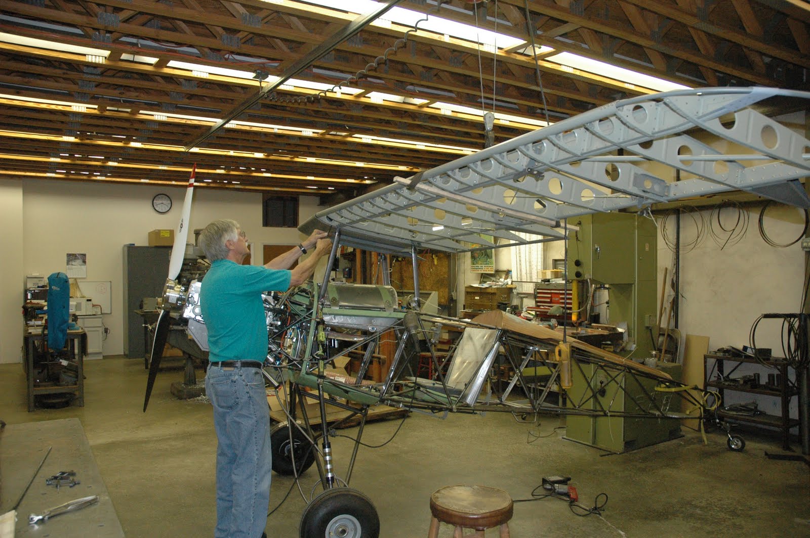
Wings Installed and Rigged


Well it's been almost 6 months since I posted to this blog!There are about 50 reasons but no good excuse for such an extended lapse. Actually there has been a little progress during the past few months but no time for posting.

As you can see from the above photos, the wings are mounted and loosely rigged. The main objective here is to make sure everything fits. I also want to weigh the airplane sans covering and paint. I can estimate the weight and c.g. of the covering and paint and arrive at a reasonably close estimate of the final weight and balance. If I get a surprise and find that it is going to be less than ideal, it will be easier to make changes prior to covering.

I recently reworked the fuel system again which I will cover in the next post.

Monday, June 28, 2010

Safety Harness


The safety harness is about 90% installed. The lap belts were anchored to the seat base tubes using a "wrap around" mount which eliminated the need for additional brackets. The lap belts will be close to the desired 45 degree angle.

The plans call for the shoulder belts to be mounted to the fuselage structure at the base of the turtle deck. I felt that this caused the belts to be angled sharply downward behind my shoulders which can cause spinal compression problems. I raised the shoulder belt penetration point to the top of the turtle deck. I will extend a cable attachment back to one of the fuse cross members near the tail. This will let the belts extend straight back from my shoulders and avoid the compression problem.

I bought the belts from Crowe Enterprises. Some of the RV guys are starting to use belts from Crowe. They make a very nice product and the price is much less than Hooker.

www.crowenterprises.com

Saturday, June 5, 2010

Landing Gear Progress


The urethane die springs in the above picture are performing well so far. That means that they are holding up the weight of the airplane and engine with no sag over time. There is no pre-load applied so far but as the wings, fuel and pilot add additional weight some preload will be necessary to maintain full ride height. The limited pre-load will give a softer "cushy" ride for the first 1 to 2 inches of gear deflection.

I intend to experiment with one additional combination of spring diameter and durometer. The current springs are 60A durometer and 2.5 inches in diameter. The next trial will be with 70A durometer and 1.75 inch diameter springs. If the smaller diameter works as well it will save about 2 pounds of unnecessary weight.

Monday, May 24, 2010

Mating the Wings

Wow,it's been quite a while since I have made enough progress to warrant a new post! Hopefully I've got things back on track for a while. We managed to mate all four wings to the fuselage and center section over the past two days.


All of the holes were pilot drilled prior to assembly except for one of the fittings on each spar.

A series of drill guide bushings and special extended drills were used to match drill the mated parts to final size.


We made up this special extended drill so we could "line drill" the holes in the forward and aft spars.


Thursday, March 11, 2010

Jabiru Engine First Run


We started the Jabiru 3300 for the first time yesterday. It started on about the second blade but ran very rich. Normal adjustments had little effect so we rolled it back inside for a closer look. We discovered a metal flake stuck in the needle and seat of the Rotec TBI fuel regulator. By the time we got it back together the rain had set in. Rain is predicted for the next few days so it might be a while before we get to run it again. Sure did sound sweet as it leaned out when we shut off the fuel.

Wednesday, February 24, 2010

Tail Wheel Progress


We shortened and de-arched the tail wheel spring. It was a little too soft in its original length. The spring is a Piper Cub unit 1-1/4" wide. It now feels good when fully loaded and has a good angle on the vertical pivot.